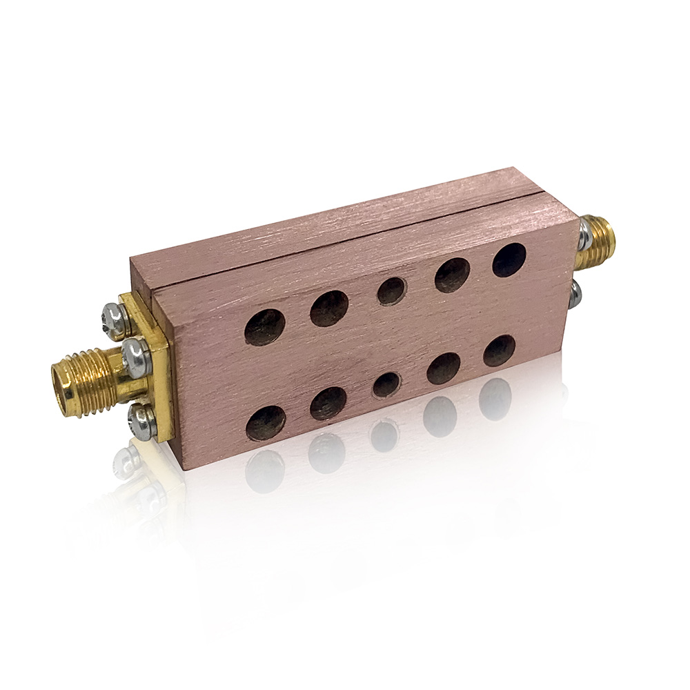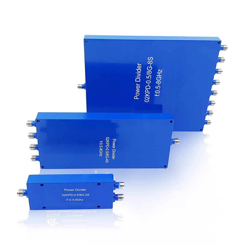
RF 2/4/8 way 500-8000MHz microstrip wilkinson power splitter/divider with SMA-Female
Technical Indicators
The technical indexes of power distributor include frequency range, bearing power, distribution loss from main circuit to branch, insertion loss between input and output, isolation between branch ports, voltage standing wave ratio of each port, etc.
1. Frequency range: This is the working premise of various RF / microwave circuits. The design structure of power distributor is closely related to the working frequency. The working frequency of the distributor must be defined before the following design can be carried out.
2. Bearing power: in the high-power distributor / synthesizer, the maximum power that the circuit element can bear is the core index, which determines what form of transmission line can be used to achieve the design task. Generally, the order of power borne by the transmission line from small to large is microstrip line, stripline, coaxial line, air stripline and air coaxial line. Which line should be selected according to the design task.
3. Distribution loss: the distribution loss from the main circuit to the branch circuit is essentially related to the power distribution ratio of the power distributor. For example, the distribution loss of two equal power dividers is 3dB and that of four equal power dividers is 6dB.
4. Insertion loss: the insertion loss between input and output is caused by the imperfect dielectric or conductor of transmission line (such as microstrip line) and considering the standing wave ratio at the input end.
5. Isolation degree: the isolation degree between branch ports is another important index of power distributor. If the input power from each branch port can only be output from the main port and should not be output from other branches, it requires sufficient isolation between branches.
6. VSWR: the smaller the VSWR of each port, the better.
Key Features
|
Feature |
Advantages |
| Ultra-wideband, 0.5 to 8 GHz | Extremely wide frequency range supports many broadband applications in a single model. |
| Low insertion loss, 0.5 dB typ. at 8 GHz | The combination of 20W power handling and low insertion loss makes this model a suitable candidate for distributing signals while maintaining excellent transmission of signal power. |
| High isolation, 22 dB typ. at 8 GHz | Minimizes interference between ports. |
| High power handling: • 16W as a splitter at 25°C • 1.5W as a combiner |
The KPD-0.5^8G-2S/4S/8S is suitable for systems with a wide range of power requirements. |
| Low amplitude unbalance, 0.04 dB at 8 GHz | Produces nearly equal output signals, ideal for parallel path and multichannel systems. |
| DC Passing, 630mA | Supports applications where DC power is needed to pass through the RF line. |
Main Indicators
| Product Name | 2Way Power Divider |
| Frequency Range | 0.5-8 GHz |
| Insertion Loss | ≤ 1.5dB(Does not include theoretical loss 3dB) |
| VSWR | IN:≤1.4: 1@500-700MHz IN:≤1.3: 1@701-8000MHzOUT:≤1.25:1 |
| Isolation | ≥20dB |
| Amplitude Balance | ≤±0.4 dB |
| Phase Balance | ≤±4° |
| Impedance | 50 OHMS |
| Power Handling | 20 Watt |
| Port Connectors | SMA-Female |
| Operating Temperature | -40℃ to +80℃ |
Main Indicators
| Product Name | 4Way Power Divider |
| Frequency Range | 0.5-8GHz |
| Insertion Loss | ≤ 2.5dB(Does not include theoretical loss 6dB) |
| VSWR | IN:≤1.4: 1 OUT:≤1.3:1 |
| Isolation | ≥20dB |
| Amplitude Balance | ≤±0.5 dB |
| Phase Balance | ≤±5° |
| Impedance | 50 OHMS |
| Power Handling | 20 Watt |
| Port Connectors | SMA-Female |
| Operating Temperature | ﹣40℃ to +80℃ |
Main Indicators
| Product Name | 8Way Power Divider |
| Frequency Range | 0.5-8 GHz |
| Insertion Loss | ≤ 4.0dB(Does not include theoretical loss 9dB) |
| VSWR | IN:≤1.55: 1@500-700MHz IN:≤1.45: 1@701-8000MHz OUT:≤1.4:1 |
| Isolation | ≥18dB |
| Amplitude Balance | ≤±0.6 dB |
| Phase Balance | ≤±6° |
| Impedance | 50 OHMS |
| Power Handling | 20 Watt |
| Port Connectors | SMA-Female |
| Operating Temperature | -40℃ to +80℃ |